
Content tagged port
Sheets as ideal forms
posted on 2018-03-05 17:30
CLIM operates on various kinds of objects. Some are connected by an inheritance, other by a composition and some are similar in a different sense.
As programmers, we often deal with the inheritance and the composition,
especially since OOP is a dominating paradigm of programming (no matter if the
central concept is the object or the function). Not so often we deal with the
third type of connection, that is the Form and the phenomena which are merely a
shadow mimicking it[1].
Let us talk about sheets. The sheet is a region[2] with an infinite resolution
and potentially infinite extent on which we can draw. Sheets may be arranged
into hierarchies creating a windowing system with a child-parent relation. Sheet
is the Form with no visual appearance. What we observe is an approximation of
the sheet which may be hard to recognize when compared to other approximations.
[1]: Theory of forms.
[2]: And many other things.
Physical devices
Sheet hierarchies may be manipulated without a physical medium but to make them
visible we need to draw them. CLIM defines ports and grafts to allow rooting
sheets to a display server. medium is defined to draw sheet approximation on
the screen[3].
How should look a square with side length 10 when drawn on a sheet? Since it doesn't have a unit we can't tell. Before we decide on a unit we choose we need to take into consideration at least the following scenarios:
If we assume device-specific unit results may drastically differ (density may vary from say 1200dpi on a printer down to 160dpi on a desktop
[4]!. The very same square could have 1cm on a paper sheet, 7cm and 10cm on different displays and 200cm on a terminal. From the perspective of a person who uses the application, this may be confusing because physical objects don't change size without a reason.Another possible approach is to assume the physical world distances measured in millimeters (or inches if you must). Thanks to that object will have a similar size on different mediums. This is better but still not good. We have to acknowledge that most computer displays are pixel based. Specifying distances in millimeters will inevitably lead to worse drawing quality
[5](compared to the situation when we use pixels as the base unit). Moreover, conversion from millimeter values to the pixel will most inevitably lead to work on floats.Some applications may have specific demands. For instance, application is meant to run on a bus stop showing arrival times. Space of the display is very limited and we can't afford approximation from the high-density specification (in pixels or millimeters) to 80x40 screen (5 lines of 8 characters with 5x8 dots each). We need to be very precise and the ability to request a particular unit size for a sheet is essential. Of course, we want to test such application on a computer screen.
I will try to answer this question in a moment. First, we have to talk about the
CLIM specification and limitations imposed by McCLIM's implementation of
grafts.
[3]: See some general recommendations.
[4]: Technically it should be PPI, not DPI (pixels per inch).
[5]: Given programmer specifies sheet size in integers (like 100x100).
Ports, grafts, and McCLIM limitations
If a port is a physical connection to a display server then graft is its screen representation. The following picture illustrates how the same physical screen may be perceived depending on its settings and the way we look at it.
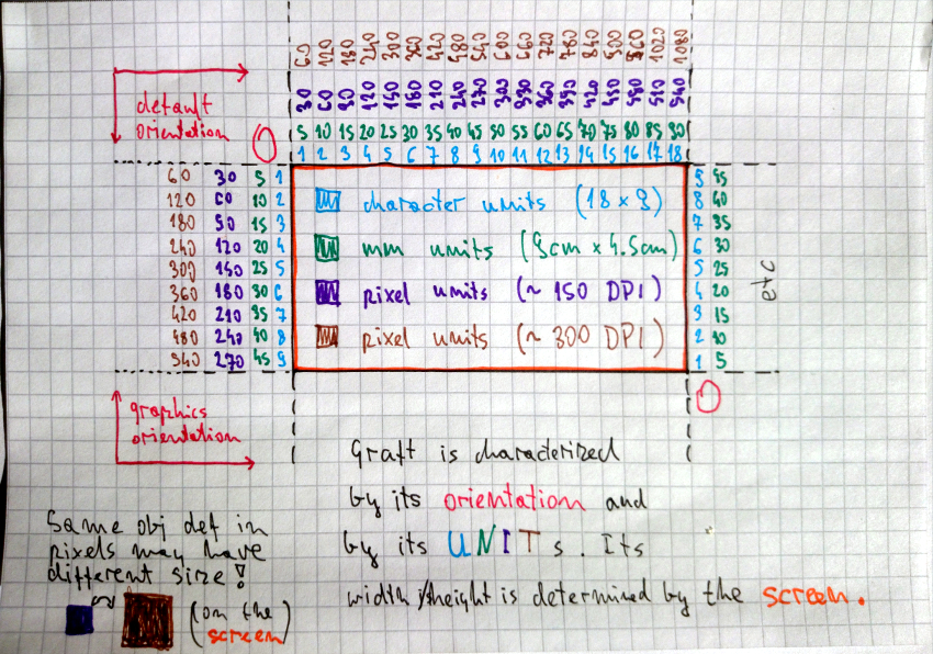
As we can see graft has an orientation (:default starts at the top-left corner
like a paper sheet and :graphics should start at the bottom left corner like
on the chart). Moreover, it has units. Currently, McCLIM will recognize
:device, :inches, :millimeters and :screen-sized [11].
That said McCLIM doesn't implement graft in a useful way. Everything is measured
in pixels (which :device units are assumed to be) and only the :default
orientation is implemented. By now we should already know that pixels are a not
a good choice for the default unit. Also, programmer doesn't have means to
request unit for a sheet (this is the API problem).
[11]: Screen size unit means that the coordinate [1/2, 1/2] is exactly in the
middle of the screens.
Physical size and pixel size compromise
We will skip the third situation, for now, to decide what unit should we default to. There are cognitive arguments for units based on a real-world distance but there are also and practical reasons against using millimeters – poor mapping to pixels and the fact that CLIM software which is already written is defined with the assumption that we operate on something comparable to a pixel.
Having all that in mind the default unit should be device-independent pixel. One of McCLIM long-term goals is to adhere to Material Design guidelines – that's why we will use dip[6] unit. 100dp has absolute value 15.875mm. On 160dpi display it is 100px, on 96dpi display it is 60px, on 240dpi display it is 150px etc. This unit gives us some nice characteristics: we are rather compatible with the existing applications and we preserving absolute distances across different screens.
[6]: Density-independent pixel.
How to draw a rectangle on the medium
Application medium may be a pixel-based screen, paper sheet or even a text terminal. When the programmer writes the application he operates on dip units which have absolute value 0.15875mm. It is the McCLIM responsibility to map these units onto the device. To be precise each graft needs to hold an extra transformation which is applied before sending content to the display server.
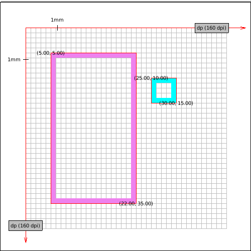
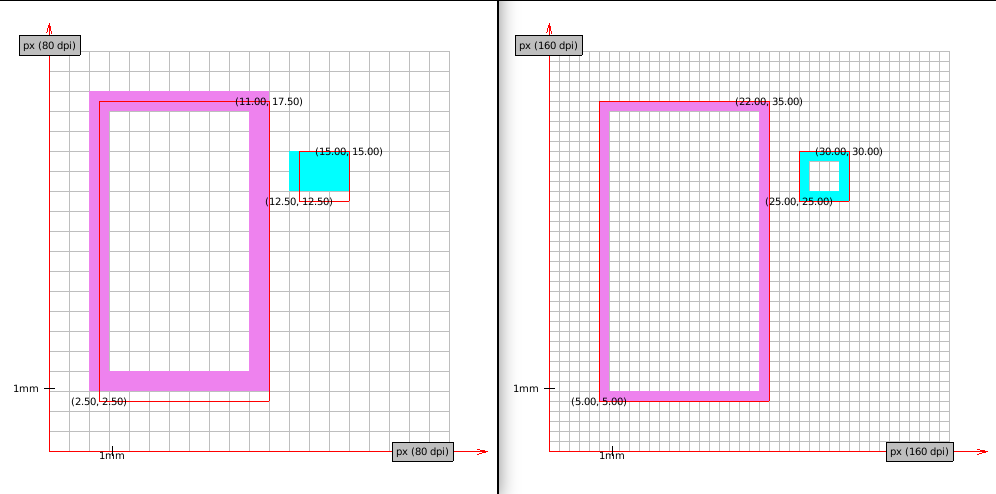
Now we will go through a few example mappings of two rectangle borders[7] drawn
on a sheet. The violet rectangle coordinates are [5,5], [22,35] and the cyan
rectangle coordinates are [25,10], [30,15].
- MDPI display device units are dip and they match native units of our choosing. No transformation is required.
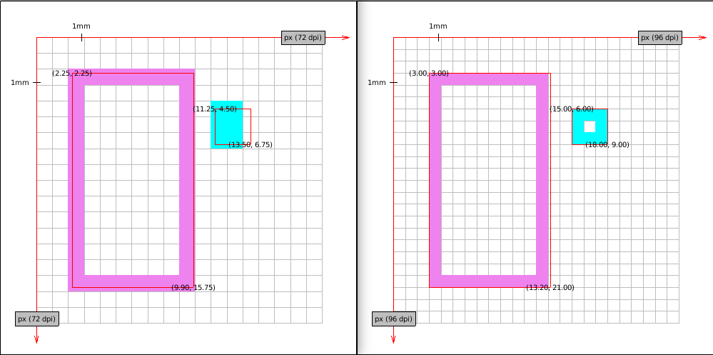
- Some old displays have density 72PPI. Not all coordinates map exactly to
pixels - we need to round them
[3]. Notice that border is thicker and that proportions are a little distorted. On the other hand despite a big change in resolution size of the object is similar in real-world values.
Windows Presentation Foundation declared 96PPI screen's pixel being the device-independent pixel because such displays were pretty common on desktops. Almost all coordinates map perfectly on this screen. Notice the approximation of the right side of the violet rectangle.
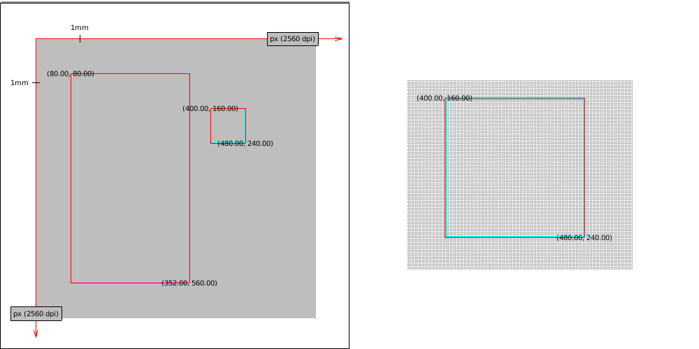
- Fact that the screen has higher density doesn't mean that coordinates mapping perfectly on a lower density screen will map well to a higher density one. Take this HDPI screen. Almost all coordinates are floats while on the MDPI display they had all integer values.
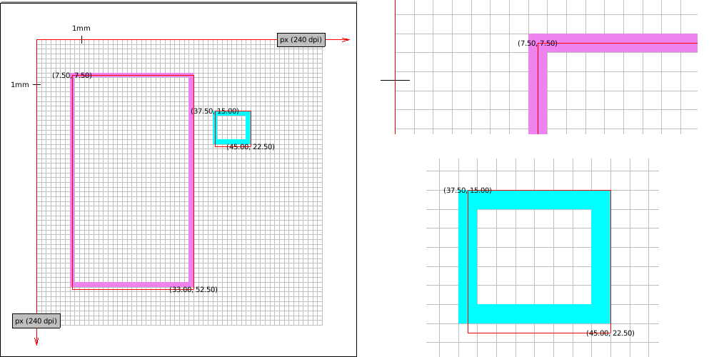
- Higher resolution makes rectangles look better (borderline is thinner and distortions are less visible to the eye). Here is XXXHDPI:
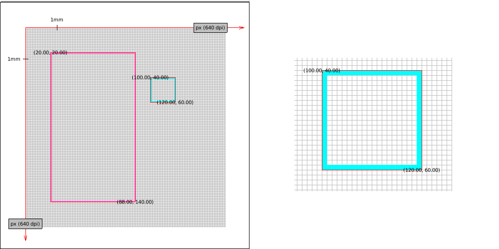
- Some printers have a really high DPI, here is imaginary 2560 DPI printer. Funnily enough its accuracy exceeds our screen density so the red border which is meant to show the "ideal" rectangle is a little off (it's fine if we scale the image though).
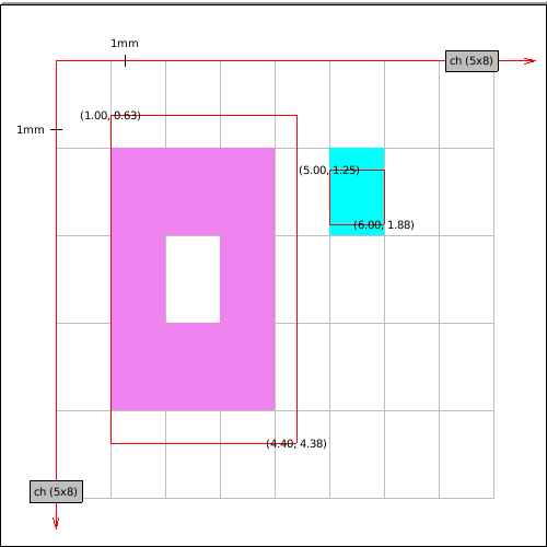
- Until now we've seen some screens with square pixels (or dots). Let's take a look at something with a really low density - a character terminal. To make the illustration better we assume an absurd terminal which has 5x8 DP per character (too small to be seen by a human eye). Notice that the real size of the rectangles is still similar.
It is time to deal with graphics orientation (Y-axis grows towards the
top). An imaginary plotter with 80DPI resolution will be used to illustrate two
solutions (the first one is wrong!). Knowing the plotter screen height is
important to know where we start the drawing.
- Graft reverts Y axis and sends the image to the plotter. Do you see what is wrong with this picture? We have defined both rectangles in default orientation, so our drawing should look similar disregarding the medium we print on. We do preserve the real size but we don't preserve the image orientation – cyan rectangle should be higher on the plot.
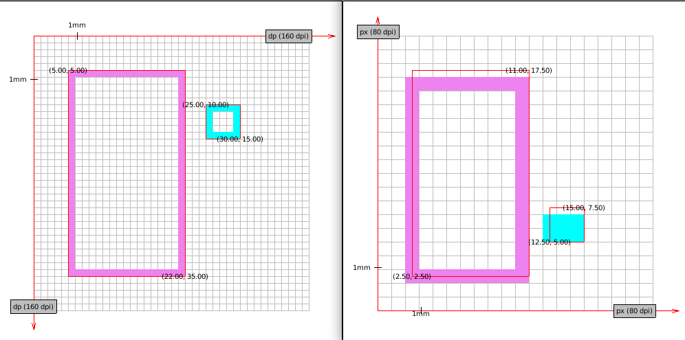
- Correct transformation involves reverting Y axis and translating objects by the screen height. See the correct transformation (on 80DPI and on MDPI plotter).
[7]: the Ideal border is composed of lines which are 1-dimensional objects
which doesn't occupy any space. Red border in drawings marks "ideal" object
boundaries. Points are labeled in device units (with possible fractions).
Sheets written with a special device in mind
There is still an unanswered question - how can we program applications with a
specific device limitations in mind? As we have discussed earlier default sheet
unit should be dip and default sheet orientation is the same as a paper
sheet's[8].
Writing an application for a terminal is different than writing an application for a web browser. The number of characters which fit on the screen is limited, drawing shapes is not practical etc. To ensure that the application is rendered correctly we need a special kind of sheet which will operate on units being characters. Take a look at the following example.
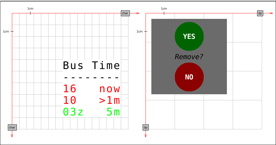
The first sheet base unit is a character of a certain physical size. We print
some information on it in various colors. Nothing prevents us from drawing a
circle[9] but that would miss the point. We use a character as a unit because
we don't want rounding and approximation. Background and foreground colors are
inherited.
The second sheet base unit is dip. It has two circles, solid grey background and a few strings (one is written in italic).
Ideally, we want to be able to render both sheets on the same physical screen. The graft and the medium will take care of the sheet approximation. The effect should look something like this.
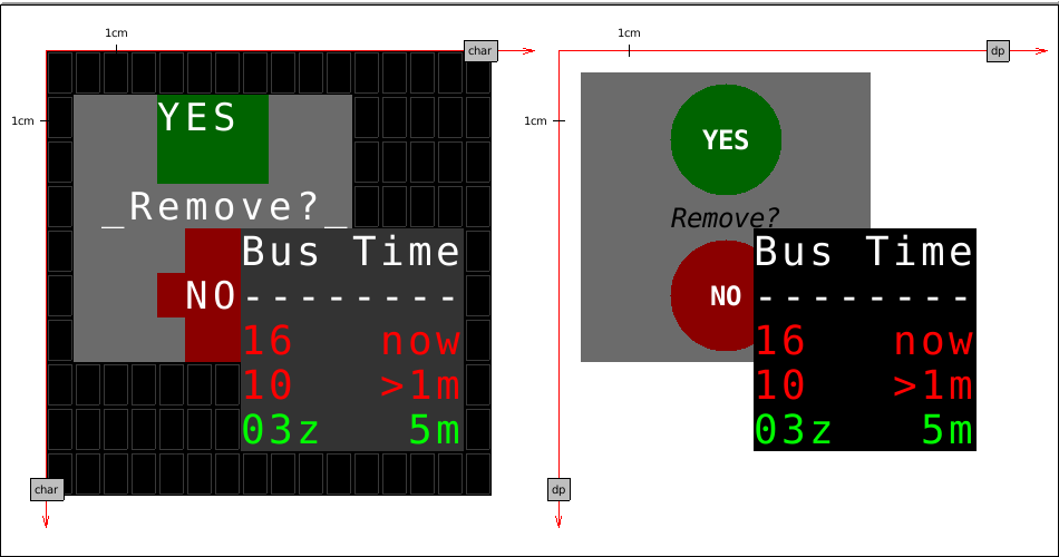
The first screen is a terminal. Circles from the second sheet are approximated with characters and look ugly but the overall effect resembles the original application. Proportions are preserved (to some degree). We see also the terminal-specialized sheet which looks exactly as we have defined it.
The second screen is mDPI display. The second sheet looks very much like something we have defined. What is more interesting though is our first sheet – it looks exactly the same as on the terminal.
[8]: Providing means to change defaults requires additional thought and is a
material for a separate chapter. McCLIM doesn't allow it yet.
[9]: As we have noted sheets are ideal planar spaces where line thickness is 0
and there is nothing preventing us from using fractions as coordinates.
Port and graft protocols
Now we know what we want. Time to think about how to achieve it. Let me remind you what kind of objects we are dealing with:
Port is a logical connection to a display server. For instance, it may contain a foreign handler which is passed to the external system API. It is responsible for the communication – configuring, writing to and reading
[10]from a device, we are connected to.Graft is a logical screen representation on which we draw. It is responsible for all transformations necessary to achieve the desired effect on the physical screen. The same port may have many associated grafts for applications with different units and orientations.
Medium is a representation of the sheet on a physical device. Sheet is the Form which is a region and may be drawn – it doesn't concern itself with physical limitations.
In the next post I will show how to implement the port and the graft (and a bit of the medium) for the charming backend. I will cover only bare minimum for mediums important to verify that graft works as expected. Complete medium implementation is the material for a separate post.
[10]: Sometimes we deal with devices which we can't take input from – for
instance a printer, a PDF render or a display without other peripherals.